To start making linetype from this shape you need to start with MKLTYPE command. Now we have the shape clearly overlapping the existing drawing.


On the next prompts of height and rotation angle simply press enter to accept the defaut values and exit the command. This will overlap the shape on existing geometry. The cursor will now have the shape, click on the midpoint of left line again as marked in the red circle in the image above. Type SHAPE and press enter, command line will prompt you to enter the name of shape which you want to insert, type CLT and press enter again. The CLT Shape file is now created and it can be used for making our linetype. Press enter and it will prompt you for a description, add the description which you want or press enter to skip this. I will use ATEXT as the name of linetype. Now the command line will prompt you to specify the name of linetype.

In my case, I am selecting desktop as the location and naming it as Sample_Ltype. Specify a location where you want to save this custom linetype and give it a name. Now type MKLTYPE and press enter, Select linetype file window will show up. MKLTYPE doesn’t recognize Mtext hence we need to convert Mtext into text using explode command before using the command. By doing so we can convert a Mtext into simple Text or single line text. Select the text as well as arrow symbols then type X and press enter. For this, we will use MKLTYPE express tool.īut before using this tool explode the text and arrow symbol. Our segment of linetype is ready and we can convert it into a linetype. After adding text and symbol make two lines of equal length as shown in the image 1. Now type A and repeat the process of adding the left pointing arrow symbol. So if you think it hasn't worked.be sure to do a regen.Now right click in the text box and select Paste from the contextual menu, you can also use Ctrl + V to paste the character.
#Get linetypes to show up in paperspace autocad 2005 update#
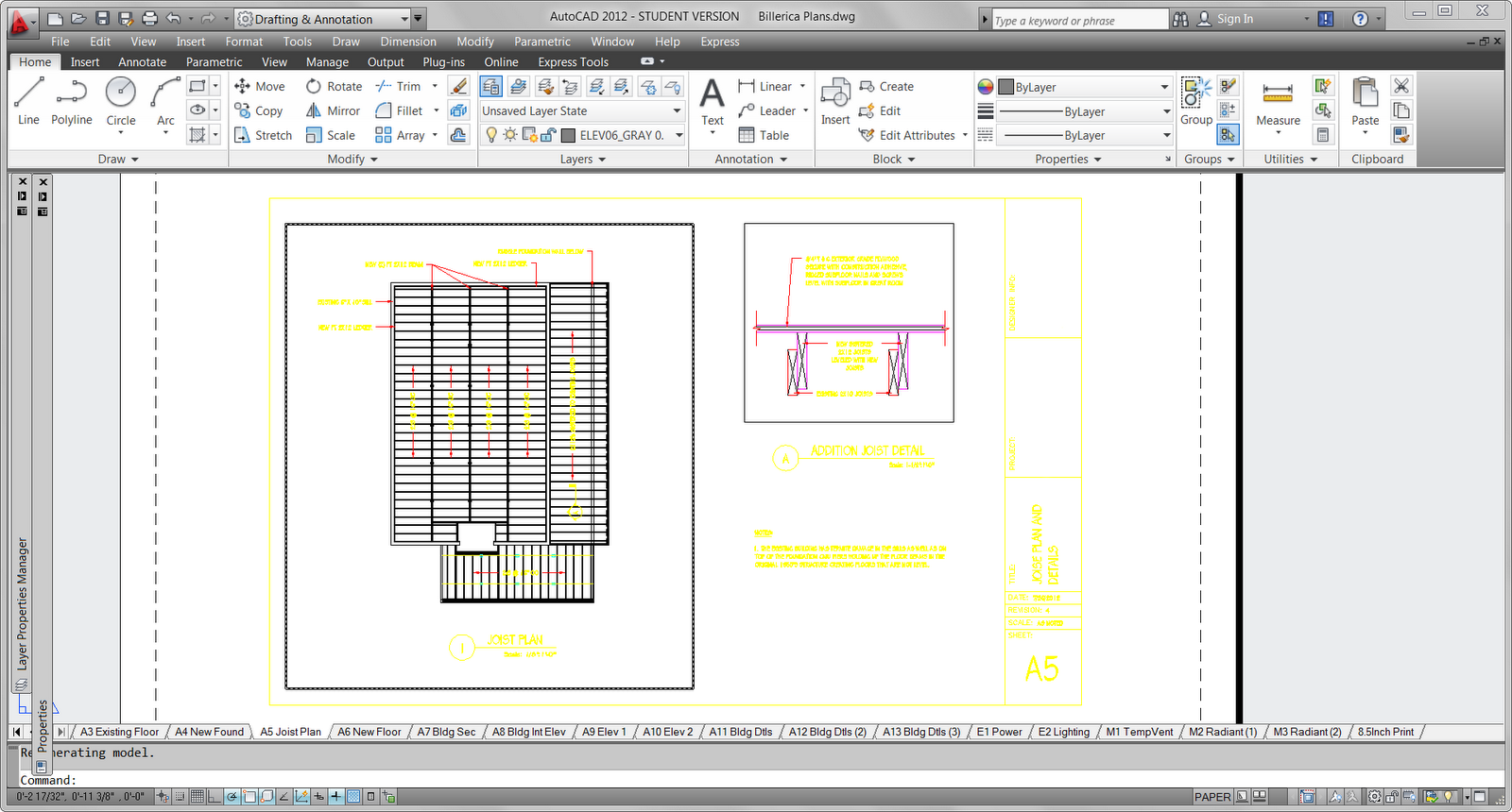
You'll need to use the REGEN or REGENALL command to update the linetypes in each viewport. When you change the PSLTSCALE or zoom within a viewport the objects are not automatically regenerated. AutoCAD does the math for you, it takes the value of the vport scale factor, and scales the linetypes according to the LTSCALE and CELTSCALE settings. So even if you have different viewports, with different magnifications - the linetypes will display the same. Setting PSLTSCALE to 1 will cause the linetype display to translate over to paper space drawing units. Why not? Because they are still based on your model space units.What to do? The PSLTSCALE system variable to the rescue. You insert your first viewport, assign a viewport scale factor and then poof - your linetypes aren't displaying properly anymore.

I receive about one email a week with this particular issue.you get all your linework set up properly in model space, all the linetypes are scaled properly and then you switch over to paper space. Tomorrow is going to be an exciting day - I get to find out about the new features in the next release of AutoCAD! The AutoCAD product team is giving some of the Autodesk employees a sneak preview.I can hardly wait! Rumor has it it's going to be really good.Ī Hip Tip to Control Linetype Scale Factors in Paper Space:


 0 kommentar(er)
